
LCR-3
Professional LCR measurement across up to 128 connections.
The LCR-3 combines Sciospec LCR measurement performance with an integrated 32-, 64- or 128-channel any-to-any multiplexer.
Components, sensor elements or test positions can remain connected while the instrument selects the required 2-, 3- or 4-port measurement configuration.
It is designed for automated batch characterization, reliability testing, sensor arrays and multi-terminal components – anywhere one LCR measurement needs to be applied repeatedly across many connections.
- 32, 64 or 128-channel any-to-any multiplexer
- High-isolation, ultra-low-parasitic reed-relay switching
- Up to 0.01% base accuracy, 0.5 ms/point and 2.4 ms switching
32 / 64 / 128
MUX CHANNELS Released physical multiplexer scale
ANY-TO-ANY
ROUTING Assign C, R, WS or W roles as the test topology changes
2.4 ms
SWITCHING Fast reconfiguration between channel states
0.01% / 0.5 ms
LCR CORE Up to 0.01% base accuracy and 0.5 ms/point
Multiplexing built for impedance measurement.
Adding a multiplexer to an LCR measurement is not only a question of adding channels. The switched path becomes part of the measurement: isolation, parasitic capacitance and routing topology matter, especially for small capacitances, high impedances and higher frequencies.
The LCR-3 integrates a high-isolation, ultra-low-parasitic reed-relay multiplexer directly with the LCR measurement electronics. Its any-to-any topology lets every MUX channel take the C, R, WS or W role, so the same instrument can scan simple DUT batches or create different 2-, 3- and 4-port connections for arrays and multi-terminal devices.
TYPICAL SCALED SETUP (LCR meter + external multiplexer): LCR meter → External scanner / matrix → Cabling / fixture interface → DUTs / fixture → Separate switching integration | LCR-3 (LCR measurement + integrated multiplexer): LCR measurement electronics → High-isolation, ultra-low-parasitic reed-relay MUX → SC98 high-density connection → DUTs / fixture → One instrument
High isolation. Very low parasitics.
The switched path matters in an impedance measurement. High-isolation, ultra-low-parasitic reed relays keep the additional electrical loading from the multiplexer low.
More than a fixed 1:N scanner
Assign C, R, WS or W to any MUX channel and define the required 2-, 3- or 4-port connection for each measurement step.
Connect the complete fixture or array once
Keep multiple DUTs or nodes connected and step through the required measurements without manual rewiring. The LCR-3 measures one configured path at a time.
2.4 ms between channel configurations
The multiplexer switches between configured states in 2.4 ms. Complete scan time also depends on measurement settings, DUT behaviour and the required sequence.
Technical Specifications
Key specifications for first technical qualification. Detailed electrical characteristics, frequency precision, measurement ranges and environmental data are available in the released datasheet.
Parameter
Specification
Details
ARCHITECTURE & MULTIPLEXING
Multiplexer channels
32, 64 or 128
Any-to-any; each MUX channel may adopt C, R, WS or W function
Measurement configurations
2-, 3- and 4-port
Sequentially switched through the integrated MUX
Switch type
High-isolation, ultra-low-parasitic reed relays
Integrated switching architecture
Switching time
2.4 ms
Between two channel configurations
Main measurement connections
4 BNC connectors
Direct 2-, 3- and 4-port configurations
MUX interface
SC98-based
One SC98 connector per 64 MUX channels; MEC1 / MDR40 connection paths in released material
MEASUREMENT
Test frequency
100 mHz ... 1 MHz
Optional 40 MHz extension
Excitation voltage
10 mV ... 1 V peak
0.1 mV resolution
Excitation current
10 µA ... 10 mA peak
1 µA resolution
Base accuracy
Up to 0.01%
See released accuracy contour below
Measurement speed
Up to 0.5 ms/point
Depends on frequency and selected measurement-quality setting
Compensation
Open-short-load
Compensates parasitic contributions from the measurement setup
EQUIVALENT-CIRCUIT MODELS & RANGES
Supported models
|Z|/θ · Zreal/Zimag · |Y|/θ · G/B · L/Q · C/D · R/Q · Rp-Cp · Rp-Lp · Rs-Cs · Rs-Ls
Two models can be visualized in parallel in time trace
Resistance / |Z|
1 mΩ ... 1 TΩ
Model / display range; accuracy depends on frequency and impedance
Capacitance
10 fF ... 1 kF
Cp and Cs models
Inductance
1 nH ... 1 TH
Lp and Ls models
SOFTWARE & PHYSICAL
Measurement software
LCR view · time trace · model selection · table view
Released software views
External control
SCPI
Via isolated full-speed USB 2.0
Form factor
Desktop or 19-inch rack-mount
Flexible system integration
Dimensions / weight
485 × 90 × 255 mm · 5.8 kg typ.
Width × height × depth
Accuracy and measurement speed
A broad central region reaches 0.01% base accuracy, with accuracy changing toward the limits of impedance and frequency.
Measurement time reaches 0.5 ms/point in the fastest setting; higher-quality settings trade speed for additional measurement stability.
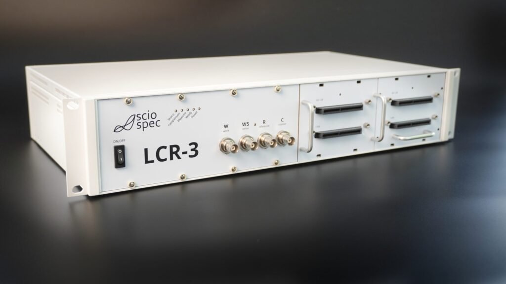
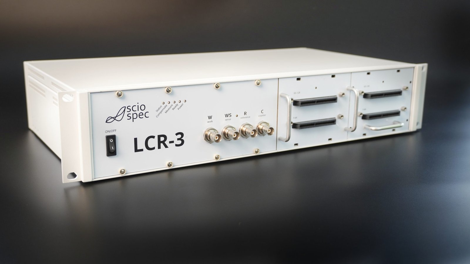
Desktop or 19-inch rack-mount.
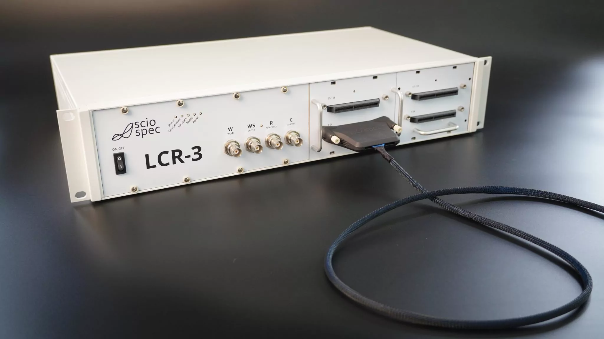
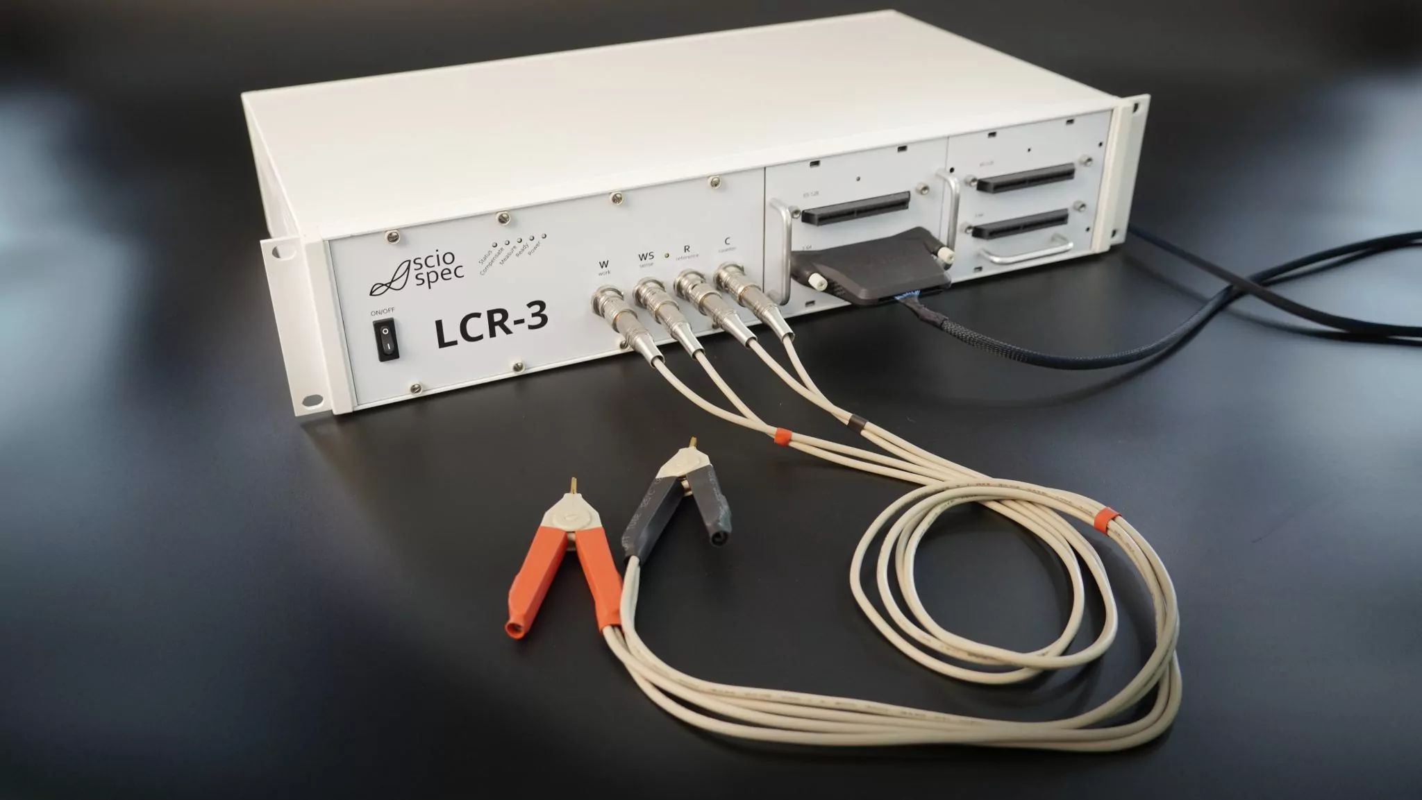
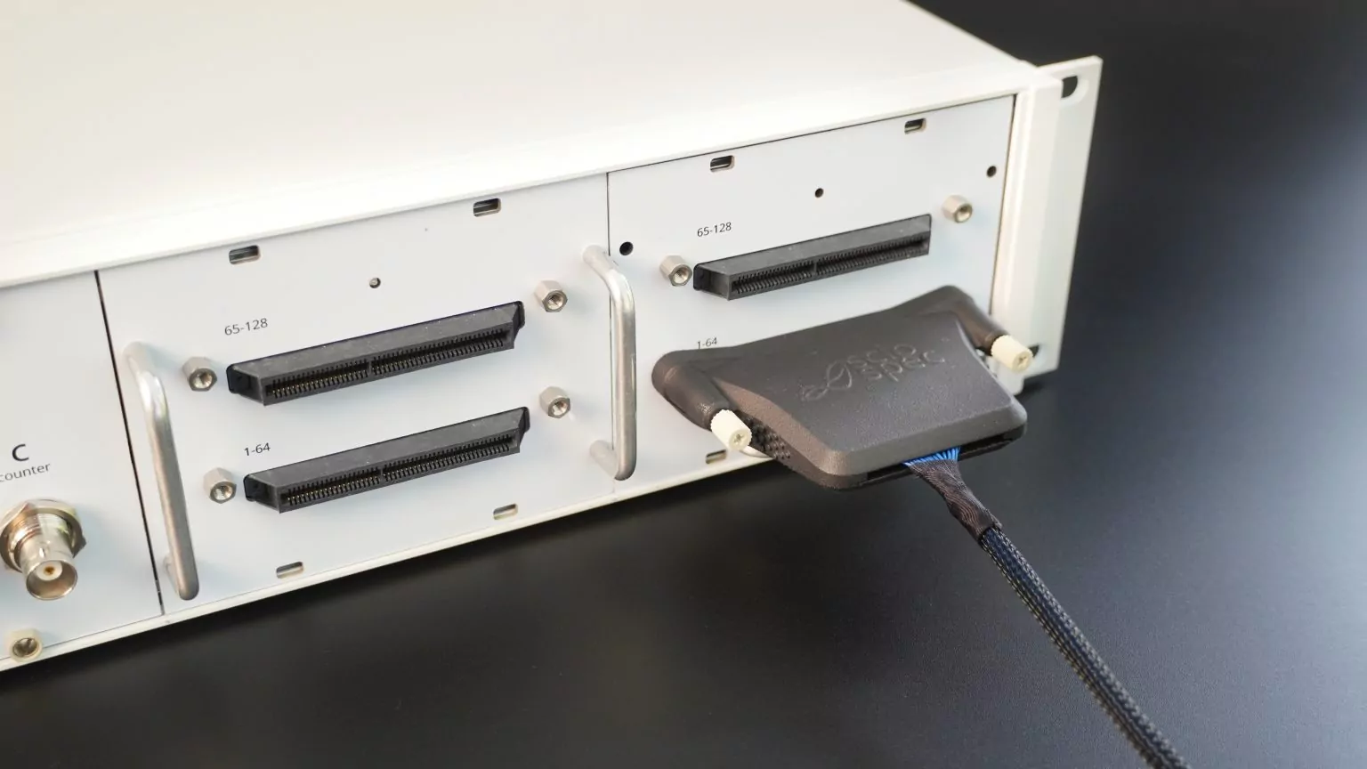
The LCR-3 is available for desktop use or rack integration. Four front BNC connectors provide direct 2-, 3- and 4-port access, while the integrated multiplexer uses high-density SC98 connections for larger fixtures, arrays and automated setups.
Final photography should show the instrument together with real MUX cabling, a fixture or array and a rack / automation context – not only isolated product beauty shots.
LCR-3 — desktop or 19-inch rack-mount instrument.

LCR-3 — desktop or 19-inch rack-mount instrument.
LCR-3 — desktop or 19-inch rack-mount instrument.
LCR-3 — desktop or 19-inch rack-mount instrument.

From direct BNC measurement to 128-channel multiplexing.
Use the four BNC connections for direct measurements, or connect larger fixtures, arrays and multiple DUT positions through the integrated multiplexer. Sciospec accessories cover common component and material formats; application-specific interfaces can be reviewed for custom fixtures and pin maps.
Direct 2-, 3- and 4-port measurements
Use the four front BNC connections for direct component measurements, setup validation and measurements that do not require multiplexing.
32, 64 or 128 switched connections
Use the SC98-based multiplexer interface and MUX cable set to connect larger fixtures, arrays or multiple DUT positions and switch between them automatically.
Adapters for custom fixtures and pin maps
For custom pin maps, sensor carriers or machine fixtures, Sciospec can review the contact map and recommend a suitable cable, adapter or application-specific interface.
Fixtures for components, SMDs, dielectrics and liquids
Available accessories include Kelvin clips, SMD and component fixtures, impedance, dielectric and liquid fixtures, a compensation kit and the MUX cable set.
Applications for multiplexed LCR measurement.
Automate repeated component measurements
Connect a tray or fixture once and scan the DUT positions in a defined sequence. Fast switching and external control support engineering QA, batch characterization and automated test stations.
Monitor many samples without reconnecting them
Keep components wired through aging, thermal or humidity tests and revisit each position automatically at defined intervals.
Measure arrays with changing node combinations
Any-to-any routing lets different contacts take C, R, WS or W roles as the required measurement pairing changes.
Test several terminal combinations automatically
Transformers, coupled inductors, component networks and other multi-pin DUTs often require several terminal combinations. Define the required measurement states once and step through them automatically.
Configure your LCR-3
Choose the form factor, multiplexer size, frequency version and accessories you need, then send the selected configuration directly for quotation. If your pin map or measurement sequence is unusual, we can review it separately.
Loading configurator…
LCR measurement software and API control
Set the measurement conditions, choose the equivalent-circuit model, view results in the LCR or table view, and follow repeated measurements in the time trace. Automated setups can control the LCR-3 externally via SCPI over the isolated USB interface.
Released software views from the 11 August 2026 datasheet: LCR view, model selection, time trace and table view.
Read the selected LCR parameters
Display the selected LCR models and measurement values in one operating view.
Choose the equivalent-circuit model
Select from the released R, L, C, impedance and admittance models.
View changes over time
Use the time-trace view for repeated or time-dependent measurements.
Control the LCR-3 from your test software
Use SCPI through the isolated USB interface to integrate the LCR-3 into automated test software.
A practical LCR subsystem for automated test equipment.
Machine builders often combine a precision LCR meter, switching hardware, cabling and control logic themselves. The LCR-3 can replace much of that stack with one rack-mountable instrument that already combines the LCR measurement and 32-, 64- or 128-channel switching.
Use the standard connection options where they fit. For dedicated fixtures or recurring machine designs, Sciospec can also review adapter PCBs, cabling and application-specific interfaces. Larger custom or OEM adaptations are scoped separately.
LCR-1, LCR-3 or ISX-3?
Choose the instrument by the job: one DUT, many sequential connections or advanced impedance spectroscopy. If several signals must be captured at exactly the same time, discuss a parallel Sciospec solution.
One DUT at a time
Compact professional LCR measurement for component characterization, inspection, troubleshooting, sensors and materials.
Many DUTs or connection points
Integrated multiplexing for batch work, arrays, reliability setups and automated test systems.
Advanced impedance spectroscopy
For experiments where detailed spectra, broader impedance-analysis workflows and EIS method depth are central.
Use a parallel system when several signals must be captured at the same instant.
Share the required channel count, timing and measurement conditions. Sciospec can recommend the appropriate parallel configuration.
Frequently Asked Questions
What does "32, 64 or 128 channels" mean on the LCR-3?
Are the LCR-3 channels measured simultaneously?
What does any-to-any multiplexing allow me to do?
How fast is the LCR-3?
What frequency range does the LCR-3 cover?
What does 0.01% base accuracy mean?
Can the LCR-3 compensate for cables and fixtures?
Can I control the LCR-3 from my own software?
When should I choose the LCR-1 instead?
When should I choose an impedance analyzer instead?
When might another architecture be more suitable?
Next steps
Configure and request a quote
Select form factor, 32 / 64 / 128 MUX, frequency version, accessories and quantity. Send the configuration directly for a concrete quotation.
Review your LCR setup
Send the DUT or fixture, contact map, required measurement combinations, frequency and scan-time target. We will review the setup and recommend a suitable configuration.
Find the right Sciospec platform
If you need simultaneous channels, advanced impedance analysis or a dedicated machine or OEM system, we will route the requirement to the appropriate Sciospec platform or engineering team.
Get in touch with us
Phone
Headquarters
Sciospec Scientific Instruments GmbH
Leipziger Str. 43b
04828 Bennewitz, Germany
Open in Google Maps