
Electrical Impedance Spectroscopy
Single- and multi-channel impedance analyzers — from compact single-channel workhorses to massive-multichannel research platforms. 100 µHz up to 100 MHz, mΩ…TΩ, in 2/3/4-electrode configurations.
For: Electrical Impedance Spectroscopy is the industry-standard technique for frequency-domain measurement of complex impedance — used across bioanalytics, batteries, materials and medical research.








Where does your EIS work start?
What is Electrical Impedance Spectroscopy?
Electrical Impedance Spectroscopy (EIS) is the industry-standard technique for frequency-domain measurement of complex impedance. Unlike DC resistance or single-frequency AC methods, EIS exploits characteristic time constants to separate bulk conduction, interfacial charge storage, transport limitations and parasitic effects that overlap in the time domain.
Terminology — EIS, dielectric spectroscopy, FRA
Because EIS is applied across diverse fields it appears under several overlapping terms. The underlying measurement is the same; only the experimental configuration changes.
Instrumentation: LCR meters, impedance analyzers, potentiostats
Several instrument classes overlap conceptually with EIS but differ fundamentally in architecture. LCR meters are bridge-based and optimized for passive component testing — they lack potentiostatic control and flexible biasing.
Electrode configurations: 2, 3 and 4-terminal
Incorrect electrode topology is among the most common causes of invalid impedance data. The validity of EIS data is determined by how the instrument couples to the sample.
Not sure which fits? Talk to an engineer — we’ll map your assay to the right hardware in one call.
One technique.
Many measurement regimes.
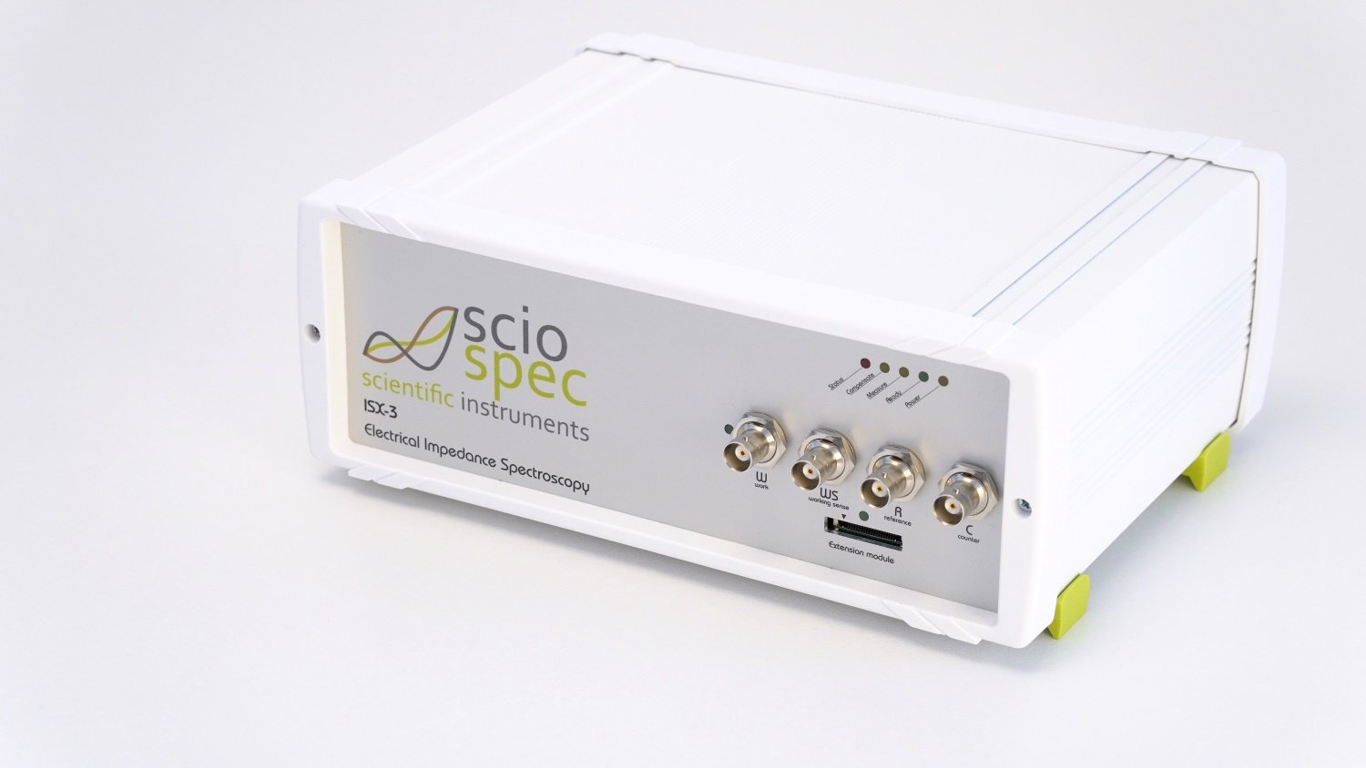
Compact ISX-3 single-channel
Compact ISX-3 single-channel workhorse
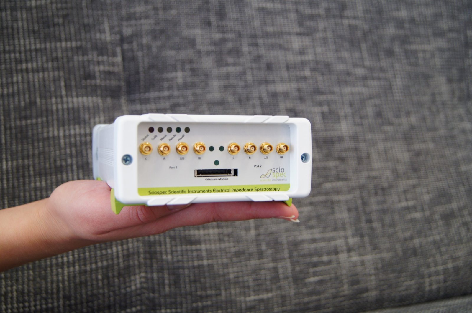
Palm-sized ISX-3mini with
Palm-sized ISX-3mini with two multiplexed channels
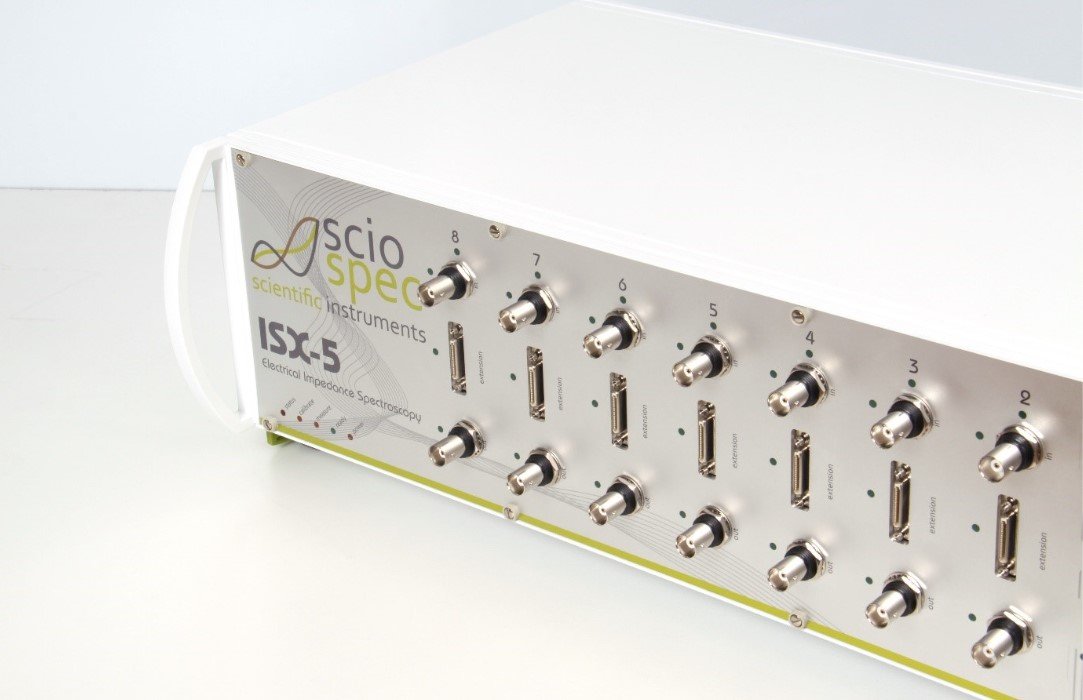
ISX-5 multichannel platform
up to 8 channels per chassis
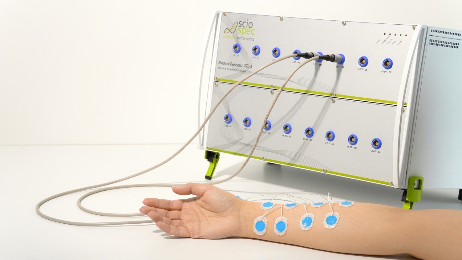
Medical Research ISX-3
Medical Research ISX-3 with IEC 60601-1 safety features
How EIS translates a sample into a spectrum
What is Electrical Impedance Spectroscopy?
Electrical Impedance Spectroscopy (EIS) is the industry-standard technique for frequency-domain measurement of complex impedance. Unlike DC resistance or single-frequency AC methods, EIS exploits characteristic time constants to separate bulk conduction, interfacial charge storage, transport limitations and parasitic effects that overlap in the time domain.
Terminology — EIS, dielectric spectroscopy, FRA
Because EIS is applied across diverse fields it appears under several overlapping terms. The underlying measurement is the same; only the experimental configuration changes.
Instrumentation: LCR meters, impedance analyzers, potentiostats
Several instrument classes overlap conceptually with EIS but differ fundamentally in architecture. LCR meters are bridge-based and optimized for passive component testing — they lack potentiostatic control and flexible biasing.
Electrode configurations: 2, 3 and 4-terminal
Incorrect electrode topology is among the most common causes of invalid impedance data. The validity of EIS data is determined by how the instrument couples to the sample.
The EIS method — in detail
What is Electrical Impedance Spectroscopy?
Electrical Impedance Spectroscopy (EIS) is the industry-standard technique for frequency-domain measurement of complex impedance. Unlike DC resistance or single-frequency AC methods, EIS exploits characteristic time constants to separate bulk conduction, interfacial charge storage, transport limitations and parasitic effects that overlap in the time domain.
Rather than collapsing system behavior into a single scalar, EIS represents the response as a complex, frequency-dependent impedance spectrum. This enables the mathematical separation of overlapping mechanisms — distinguishing immediate bulk conduction from slower diffusion events — without destroying or significantly perturbing the system under test.
Terminology — EIS, dielectric spectroscopy, FRA
Because EIS is applied across diverse fields it appears under several overlapping terms. The underlying measurement is the same; only the experimental configuration changes.
- Electrical Impedance Spectroscopy — frequency-resolved measurement of impedance
- Electrochemical Impedance Spectroscopy — same technique applied to ionic systems
- Dielectric Spectroscopy — broader physics term, materials science focus
- AC Impedance — emphasizes alternating current nature
- FRA (Frequency Response Analysis) — hardware sweeping technique
Instrumentation: LCR meters, impedance analyzers, potentiostats
Several instrument classes overlap conceptually with EIS but differ fundamentally in architecture. LCR meters are bridge-based and optimized for passive component testing — they lack potentiostatic control and flexible biasing.
Impedance analyzers are explicitly designed for frequency-resolved analysis across wide frequency and impedance ranges, with controlled excitation amplitudes and DC biasing. Potentiostats excel at defining electrochemical operating points but typically constrain frequency range and parallelization. Network analyzers target RF/microwave regimes unsuitable for low-frequency biological or electrochemical work.
Electrode configurations: 2, 3 and 4-terminal
Incorrect electrode topology is among the most common causes of invalid impedance data. The validity of EIS data is determined by how the instrument couples to the sample.
- 2-electrode — acceptable only for high-impedance dielectrics
- 3-electrode — adds a reference for controlled bias in electrochemistry
- 4-electrode (Kelvin) — separates current injection from voltage sensing, required for batteries and conductive fluids
- Independent Force / Sense paths are required for mΩ-regime accuracy
Signal-chain artifacts and how to avoid them
Recognizing instrumental artifacts is critical for valid modeling. Apparent inductive features at high frequencies are most often introduced by cabling and connectors rather than the sample under test.
- Inductive tails — caused by cabling inductance above ~100 kHz
- Capacitive shunting — parasitic capacitance shorting high-impedance samples
- Contact resistance — resolved by switching to 4-electrode (Kelvin)
- Kramers–Kronig validation tests causality and linearity
- Excitation amplitude must stay in the linear regime (mV)
Scaling from lab bench to production
Industrial environments rarely tolerate serial measurements. Multiplexing increases channel count but sacrifices simultaneity and introduces parasitic effects along the signal chain. Parallel architectures preserve interpretability but impose strict synchronization requirements.
Purpose-built multi-channel platforms — like the ISX-5 and CSX-64 — integrate these constraints at the hardware level rather than scaling single-channel designs. When EIS becomes a subsystem in a larger product, OEM measurement modules transfer integration risk and lifecycle overhead from the product team to the measurement supplier.
Application examples
EIS is applicable wherever electrical properties encode information about structure, composition or state.
- Materials & dielectrics — bulk and interfacial characterization
- Component testing — capacitors, micro-storage devices, sensors
- Bioanalytics & organ-on-chip — barrier integrity, cell assays
- Batteries & fuel cells — degradation, internal resistance, diffusion
- Electrochemical biosensors — transducer for binding events
- Medical research — bio-impedance with 60601-1 safe front-ends
EIS vs. neighbouring techniques
| Technique | Frequency domain | Best for | Limitation |
|---|---|---|---|
| EIS | 1 µHz – 100 MHz | Complex impedance of any system | Requires quasi-stationarity |
| LCR meter | Discrete spot frequencies | Passive component QA | No bias control, no electrochemistry |
| Potentiostat | DC + limited FRA | Electrochemical operating point | Narrow FRA range, often serial |
| Network analyzer | RF / microwave | Scattering parameters | Poor low-frequency / high-Z |
| EIT | Spatial reconstruction | Conductivity maps in 2D / 3D | Massive electrode arrays required |
Same underlying physics — instrument architecture determines which problems it can solve.
- Palm-sized ISX-3mini with two multiplexed channels
- ISX-5 multichannel platform — up to 8 channels per chassis
- Medical Research ISX-3 with IEC 60601-1 safety features
- ISX-3 EIT combines EIS + EIT in one instrument
- ExtensionPort for custom application-specific front-ends
Table of Contents
Recommended systems
Frequently asked questions
What is Electrochemical Impedance Spectroscopy (EIS)?
EIS measures the complex impedance of a material or electrochemical system over a range of frequencies. A small sinusoidal excitation is applied and the current response is analysed to determine how the system resists or stores energy.
It provides detailed insight into charge transfer, diffusion, double-layer formation and other interfacial processes — making it essential for batteries, biosensors, corrosion research and material interfaces.
What is the fundamental difference between an impedance analyzer and a standard LCR meter?
An impedance analyzer is a precision instrument optimized for broadband complex impedance spectroscopy, whereas a standard LCR meter is typically designed for single-point or limited-frequency component parameter estimation. While LCR meters often utilize bridge methods for high-accuracy component binning, impedance analyzers generally employ current-voltage (I/V) methods to maintain high dynamic range and precision across wide frequency sweeps. The analyzer generates frequency-dependent spectra, such as Bode and Nyquist plots, using phase-sensitive detection to characterize the reactive and resistive components of a system under test.
When should a dedicated impedance analyzer be chosen over a Vector Network Analyzer (VNA)?
A dedicated impedance analyzer is the preferred tool for high-precision characterization in the millihertz to 100 MHz regime, particularly when the Device Under Test (DUT) exhibits a wide absolute impedance range spanning from mΩ to TΩ. VNAs are RF-centric instruments utilizing a fixed reference impedance (typically 50 Ω) for S-parameter measurement in the high-frequency and microwave regimes. While VNAs are powerful for GHz-regime reflection measurements, they lack the low-frequency accuracy and high dynamic range required for materials characterization, bioimpedance, or electrochemical spectroscopy.
What is the distinction between Electrochemical Impedance Spectroscopy (EIS) and general impedance analysis?
Electrochemical Impedance Spectroscopy (EIS) is a specific subset of impedance analysis that characterizes systems, such as batteries or biosensors, under controlled DC potentials (potentiostatic) or currents (galvanostatic). While a general-purpose impedance analyzer characterizes passive components and materials, EIS requires hardware—often a potentiostat or specialized analyzer like the ISX-3—capable of maintaining electrochemical stability while sweeping the AC excitation signal. This methodology allows for the study of interfacial kinetics, mass transport, and state-of-health (SoH) diagnostics in energy and biological systems.
How should "base accuracy" be interpreted when selecting an impedance analyzer?
Base accuracy is a single-point specification that rarely reflects real-world performance across a wide operational envelope; evaluators must instead rely on accuracy-contour plots to determine precision at specific frequency and impedance magnitude intersections. Accuracy is highly dependent on both the test frequency and the absolute value of the measured impedance. For instance, a precision instrument may offer 0.01% accuracy between 1 Ω and 1 GΩ up to 2 MHz, but this degrades significantly as measurements approach frequency limits or extreme impedance values.
What are the trade-offs between sequential multiplexing and fully parallel multichannel architectures?
Sequential multiplexing utilizes a single measurement core to scan multiple ports, offering a cost-effective solution for slow-changing systems, while fully parallel architectures provide simultaneous acquisition for higher time resolution and throughput. Multiplexed systems (e.g., MUX32/64 modules) can scale to a high number of ports but are limited by switching speeds and sequential scan times. Fully parallel systems, such as the ISX-5, eliminate switching latency and are critical for capturing transient phenomena or synchronizing massive sensor arrays in automated test equipment (ATE).
Can an impedance analyzer be effectively integrated into automated test equipment (ATE) or OEM products?
Yes, an impedance analyzer can be integrated into complex systems using modular measurement cores or embedded boards that bypass the need for custom analog front-end development. Sciospec’s OEM solutions provide pre-calibrated measurement technology that can be seamlessly embedded into diagnostic devices or industrial setups. These platforms support headless operation through native SDKs (Python, C++, LabVIEW) and feature fast hardware synchronization, isolated I/O, and trigger capabilities for tight integration into automated software stacks.
When is a four-terminal (Kelvin) connection scheme mandatory for impedance measurements?
A four-terminal (4-wire) connection is required whenever the lead and contact resistance of the test setup approach the magnitude of the DUT impedance, or when high-frequency parasitics threaten measurement stability. By using separate pairs for excitation current and voltage sensing, the Kelvin connection eliminates the voltage drop across the measurement leads from the final result. This is essential for low-impedance applications such as battery diagnostics or when characterising high-performance electronic components.
Can an oscilloscope or a standard multimeter be used as a substitute for an impedance analyzer?
No, while an oscilloscope can visualize phase shifts between voltage and current, it lacks the precision current sensing, phase-sensitive detection, and automated frequency sweep capabilities required for valid impedance spectroscopy. Multi-meters are basic tools for single-point resistance or capacitance measurement and cannot generate the complex impedance spectra (Z = R + jX) necessary for research or industrial characterization. Only dedicated analyzers provide the dynamic range, frequency resolution, and modeling support required for technically sophisticated applications.
What are the primary challenges when measuring high DC-bias devices like batteries or semiconductors?
Handling high DC bias requires an analyzer with integrated bias control or external interface modules to prevent the measurement front-end from saturating under the DC load. In battery applications, the instrumentation must handle high discharge currents while maintaining a small-signal AC excitation for spectroscopy, often requiring specialized fixtures and safety derating. For semiconductors, precise voltage bias is critical for mapping performance under realistic operating conditions without inducing catastrophic failure of the DUT or the instrumentation.
When is a precision impedance analyzer not the appropriate tool for an application?
A precision impedance analyzer is unsuitable for GHz-regime microwave testing, basic low-accuracy continuity checks, or safety-critical clinical monitoring where bedside-specific medical workflows are mandated. It is not a cost-effective choice for simple, fixed-frequency 1% accuracy LCR checks or “plug-and-play” use by non-experts without a background in equivalent circuit modeling. Furthermore, if the application requires high-power characterization beyond standard instrument limits, external power interfaces and meticulous safety protocols are mandatory.
How do I choose the right impedance analyzer for my application?
Choosing the right impedance analyzer depends on frequency range, impedance range, measurement accuracy, and system architecture. Key parameters include frequency coverage (from mHz to MHz or higher), impedance range (from mΩ to TΩ), and how accuracy varies across this range. In addition, channel count, multichannel capability, and integration requirements such as API access or automation support play a critical role. For applications like bioimpedance, electrochemical impedance spectroscopy (EIS), or material characterization, broadband impedance analyzers with high dynamic range are required, while simpler component testing may be sufficiently covered by an LCR meter.
How can impedance analyzers be integrated into automated test systems (ATE)?
Modern impedance analyzers are designed for seamless integration into automated test equipment (ATE) and industrial environments. Integration is typically achieved through software APIs and hardware control interfaces, including SDKs for Python, C++, or LabVIEW, as well as remote control via USB or Ethernet. Many systems support hardware trigger inputs and outputs for synchronization with external equipment and allow headless operation without a graphical user interface. These features enable impedance measurement systems to operate as embedded components within automated workflows, production lines, or OEM devices.
What is the difference between multiplexed and parallel multichannel impedance measurement?
Multiplexed multichannel impedance measurement uses a single measurement core that sequentially scans multiple channels, offering a cost-effective solution for systems with slow dynamics. In contrast, parallel multichannel impedance measurement uses multiple measurement cores to acquire data simultaneously across channels, enabling significantly higher temporal resolution. The choice between multiplexing and parallel architectures depends on the required measurement speed, system dynamics, and throughput, with parallel systems being essential for time-sensitive or high-throughput applications.
How does measurement speed affect impedance spectroscopy results?
Measurement speed in impedance spectroscopy is determined by acquisition time per frequency point, number of frequencies per sweep, and system architecture. Faster measurements reduce total test time but may affect signal stability and accuracy, particularly at low frequencies where longer integration times are required. In multichannel systems, speed is also influenced by whether channels are measured sequentially through multiplexing or simultaneously using parallel acquisition. Optimizing measurement speed requires balancing throughput, resolution, and accuracy based on the application.
How accurate are impedance analyzers across different frequencies?
Impedance analyzer accuracy varies significantly across frequency and impedance range. While base accuracy specifications describe performance at specific conditions, real-world measurement accuracy depends on frequency, impedance magnitude, and the measurement setup, including cabling and fixtures. Accuracy contour plots provide a more realistic representation of performance across the full operating range and are essential for evaluating how an impedance analyzer will perform in a given application.
Can impedance analyzers be used for battery and electrochemical measurements?
Impedance analyzers are widely used for battery testing and electrochemical impedance spectroscopy (EIS), where they provide insight into processes such as charge transfer, diffusion, and degradation. These applications require stable AC excitation signals, precise phase measurement, and often controlled DC bias conditions. In many cases, additional hardware such as potentiostats or bias units is required to ensure accurate impedance measurement under real operating conditions.
Can EIS be scaled beyond single-sample lab setups?
Is EIS suitable for OEM or embedded integration?
Can EIS be performed on non-stationary systems?
Frequently asked questions
What is Electrochemical Impedance Spectroscopy (EIS)?
EIS measures the complex impedance of a material or electrochemical system over a range of frequencies. A small sinusoidal excitation is applied and the current response is analysed to determine how the system resists or stores energy.
It provides detailed insight into charge transfer, diffusion, double-layer formation and other interfacial processes — making it essential for batteries, biosensors, corrosion research and material interfaces.
What is the fundamental difference between an impedance analyzer and a standard LCR meter?
An impedance analyzer is a precision instrument optimized for broadband complex impedance spectroscopy, whereas a standard LCR meter is typically designed for single-point or limited-frequency component parameter estimation. While LCR meters often utilize bridge methods for high-accuracy component binning, impedance analyzers generally employ current-voltage (I/V) methods to maintain high dynamic range and precision across wide frequency sweeps. The analyzer generates frequency-dependent spectra, such as Bode and Nyquist plots, using phase-sensitive detection to characterize the reactive and resistive components of a system under test.
When should a dedicated impedance analyzer be chosen over a Vector Network Analyzer (VNA)?
A dedicated impedance analyzer is the preferred tool for high-precision characterization in the millihertz to 100 MHz regime, particularly when the Device Under Test (DUT) exhibits a wide absolute impedance range spanning from mΩ to TΩ. VNAs are RF-centric instruments utilizing a fixed reference impedance (typically 50 Ω) for S-parameter measurement in the high-frequency and microwave regimes. While VNAs are powerful for GHz-regime reflection measurements, they lack the low-frequency accuracy and high dynamic range required for materials characterization, bioimpedance, or electrochemical spectroscopy.
What is the distinction between Electrochemical Impedance Spectroscopy (EIS) and general impedance analysis?
Electrochemical Impedance Spectroscopy (EIS) is a specific subset of impedance analysis that characterizes systems, such as batteries or biosensors, under controlled DC potentials (potentiostatic) or currents (galvanostatic). While a general-purpose impedance analyzer characterizes passive components and materials, EIS requires hardware—often a potentiostat or specialized analyzer like the ISX-3—capable of maintaining electrochemical stability while sweeping the AC excitation signal. This methodology allows for the study of interfacial kinetics, mass transport, and state-of-health (SoH) diagnostics in energy and biological systems.
How should "base accuracy" be interpreted when selecting an impedance analyzer?
Base accuracy is a single-point specification that rarely reflects real-world performance across a wide operational envelope; evaluators must instead rely on accuracy-contour plots to determine precision at specific frequency and impedance magnitude intersections. Accuracy is highly dependent on both the test frequency and the absolute value of the measured impedance. For instance, a precision instrument may offer 0.01% accuracy between 1 Ω and 1 GΩ up to 2 MHz, but this degrades significantly as measurements approach frequency limits or extreme impedance values.
What are the trade-offs between sequential multiplexing and fully parallel multichannel architectures?
Sequential multiplexing utilizes a single measurement core to scan multiple ports, offering a cost-effective solution for slow-changing systems, while fully parallel architectures provide simultaneous acquisition for higher time resolution and throughput. Multiplexed systems (e.g., MUX32/64 modules) can scale to a high number of ports but are limited by switching speeds and sequential scan times. Fully parallel systems, such as the ISX-5, eliminate switching latency and are critical for capturing transient phenomena or synchronizing massive sensor arrays in automated test equipment (ATE).
Can an impedance analyzer be effectively integrated into automated test equipment (ATE) or OEM products?
Yes, an impedance analyzer can be integrated into complex systems using modular measurement cores or embedded boards that bypass the need for custom analog front-end development. Sciospec’s OEM solutions provide pre-calibrated measurement technology that can be seamlessly embedded into diagnostic devices or industrial setups. These platforms support headless operation through native SDKs (Python, C++, LabVIEW) and feature fast hardware synchronization, isolated I/O, and trigger capabilities for tight integration into automated software stacks.
When is a four-terminal (Kelvin) connection scheme mandatory for impedance measurements?
A four-terminal (4-wire) connection is required whenever the lead and contact resistance of the test setup approach the magnitude of the DUT impedance, or when high-frequency parasitics threaten measurement stability. By using separate pairs for excitation current and voltage sensing, the Kelvin connection eliminates the voltage drop across the measurement leads from the final result. This is essential for low-impedance applications such as battery diagnostics or when characterising high-performance electronic components.
Can an oscilloscope or a standard multimeter be used as a substitute for an impedance analyzer?
No, while an oscilloscope can visualize phase shifts between voltage and current, it lacks the precision current sensing, phase-sensitive detection, and automated frequency sweep capabilities required for valid impedance spectroscopy. Multi-meters are basic tools for single-point resistance or capacitance measurement and cannot generate the complex impedance spectra (Z = R + jX) necessary for research or industrial characterization. Only dedicated analyzers provide the dynamic range, frequency resolution, and modeling support required for technically sophisticated applications.
What are the primary challenges when measuring high DC-bias devices like batteries or semiconductors?
Handling high DC bias requires an analyzer with integrated bias control or external interface modules to prevent the measurement front-end from saturating under the DC load. In battery applications, the instrumentation must handle high discharge currents while maintaining a small-signal AC excitation for spectroscopy, often requiring specialized fixtures and safety derating. For semiconductors, precise voltage bias is critical for mapping performance under realistic operating conditions without inducing catastrophic failure of the DUT or the instrumentation.
When is a precision impedance analyzer not the appropriate tool for an application?
A precision impedance analyzer is unsuitable for GHz-regime microwave testing, basic low-accuracy continuity checks, or safety-critical clinical monitoring where bedside-specific medical workflows are mandated. It is not a cost-effective choice for simple, fixed-frequency 1% accuracy LCR checks or “plug-and-play” use by non-experts without a background in equivalent circuit modeling. Furthermore, if the application requires high-power characterization beyond standard instrument limits, external power interfaces and meticulous safety protocols are mandatory.
How do I choose the right impedance analyzer for my application?
Choosing the right impedance analyzer depends on frequency range, impedance range, measurement accuracy, and system architecture. Key parameters include frequency coverage (from mHz to MHz or higher), impedance range (from mΩ to TΩ), and how accuracy varies across this range. In addition, channel count, multichannel capability, and integration requirements such as API access or automation support play a critical role. For applications like bioimpedance, electrochemical impedance spectroscopy (EIS), or material characterization, broadband impedance analyzers with high dynamic range are required, while simpler component testing may be sufficiently covered by an LCR meter.
How can impedance analyzers be integrated into automated test systems (ATE)?
Modern impedance analyzers are designed for seamless integration into automated test equipment (ATE) and industrial environments. Integration is typically achieved through software APIs and hardware control interfaces, including SDKs for Python, C++, or LabVIEW, as well as remote control via USB or Ethernet. Many systems support hardware trigger inputs and outputs for synchronization with external equipment and allow headless operation without a graphical user interface. These features enable impedance measurement systems to operate as embedded components within automated workflows, production lines, or OEM devices.
What is the difference between multiplexed and parallel multichannel impedance measurement?
Multiplexed multichannel impedance measurement uses a single measurement core that sequentially scans multiple channels, offering a cost-effective solution for systems with slow dynamics. In contrast, parallel multichannel impedance measurement uses multiple measurement cores to acquire data simultaneously across channels, enabling significantly higher temporal resolution. The choice between multiplexing and parallel architectures depends on the required measurement speed, system dynamics, and throughput, with parallel systems being essential for time-sensitive or high-throughput applications.
How does measurement speed affect impedance spectroscopy results?
Measurement speed in impedance spectroscopy is determined by acquisition time per frequency point, number of frequencies per sweep, and system architecture. Faster measurements reduce total test time but may affect signal stability and accuracy, particularly at low frequencies where longer integration times are required. In multichannel systems, speed is also influenced by whether channels are measured sequentially through multiplexing or simultaneously using parallel acquisition. Optimizing measurement speed requires balancing throughput, resolution, and accuracy based on the application.
How accurate are impedance analyzers across different frequencies?
Impedance analyzer accuracy varies significantly across frequency and impedance range. While base accuracy specifications describe performance at specific conditions, real-world measurement accuracy depends on frequency, impedance magnitude, and the measurement setup, including cabling and fixtures. Accuracy contour plots provide a more realistic representation of performance across the full operating range and are essential for evaluating how an impedance analyzer will perform in a given application.
Can impedance analyzers be used for battery and electrochemical measurements?
Impedance analyzers are widely used for battery testing and electrochemical impedance spectroscopy (EIS), where they provide insight into processes such as charge transfer, diffusion, and degradation. These applications require stable AC excitation signals, precise phase measurement, and often controlled DC bias conditions. In many cases, additional hardware such as potentiostats or bias units is required to ensure accurate impedance measurement under real operating conditions.
When is a four-electrode (Kelvin) configuration strictly required?
Can EIS be scaled beyond single-sample lab setups?
Is EIS suitable for OEM or embedded integration?
Why do high-frequency Nyquist plots often show apparent inductive behavior?
Can EIS be performed on non-stationary systems?
How is EIS data validity assessed beyond visual inspection?
What practically determines the lowest usable frequency?
Why is the Constant Phase Element (CPE) important?
How does EIS compare to Cyclic Voltammetry?
Find the right EIS setup for your measurement
The right impedance analyzer for every need
Use it as an external ExtensionPort module, integrate it into selected Sciospec instruments, or ask us to review compatibility with measurement equipment you already use.
Impedance Analyzer – Scalable Precision for Every Application
Sciospec impedance analyzers combine high measurement precision with full adaptability. From research and material development to medical technology and industrial end-of-line testing – we provide the system that fits. Our analyzers cover frequency ranges from millihertz to hundreds of megahertz and deliver up to 0.01% base accuracy – even with complex, dynamic impedance curves.
One Platform – Countless Possibilities
Our modular technology covers the full range: from portable single-channel instruments to fully integrated multi-channel analyzers with hundreds of channels. Whether you need sequential acquisition via multiplexer or fully parallel setups for maximum time resolution – our systems scale with your task. This flexibility makes them ideal for high-throughput testing, sensor characterization or production environments where reliable data matters.
Modular, Expandable, OEM-Ready
Our platform is designed to grow: start with one channel and expand as needed – through multiplexers, OEM modules or tailored sensor interfaces. We also support full OEM integration, from diagnostics modules to embedded electronics. Looking for an analyzer that adapts to your needs – not the other way around? Let’s talk about your application.
Available options
- Frontpanel connectors: BNC, SMA, MCX, DSUB, custom
- Internal multiplexer (32 …128 port any-to-any) options for sequential multichannel capabilities
- IOport digital interface connector for external sensors and other hardware
- Wireless interfaces
- Medical grade modifications
- Power supply
- Enclosure modification
- Isolated USB-Port
- AC coupling frontend
- Temperature controller module
- Precision multichannel temperature monitoring module for most common temperature sensor types
- Customized current and voltage ranges
- 2nd measurement channel (default for ISX-3 mini / optional for ISX-3)
- Battery operation
- And many more
Impedance Analyzers Basics
When measuring complex impedance, the required measurement setup can be divided into four different components:
- An excitation signal source to generate a stimulus signal that can be applied to the device/object under test (DUT)
- The contacting and cabling setup to connect the DUT to the instrumentation.
- The measurement frontend responsible for picking up the relevant measurement signals from the DUT and amplifying/preprocessing them in the analog domain for the detector.
- A detector/demodulator that extracts the relevant complex information from the acquired signals.
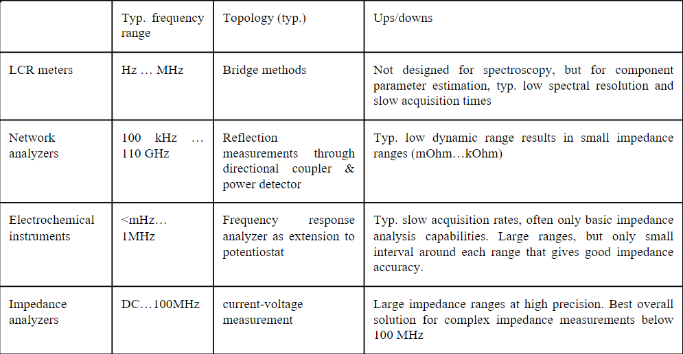
Different combinations and parameterization of these components make up the overall impedance measurement setups and some of them are so commonly used, that they are integrated in different classes of instruments. The most common instrument types to measure complex impedance are:
- LCR meters
- network analyzers
- electrochemical equipment
- impedance analyzer
- Other (time domain analyzers, oscilloscopes, spectrum analyzers, …)
Sciospec offers a broad range of solutions for impedance measurement spanning most of these classes.
Impedance analyzer specifications – what to watch out for
When measuring electrical impedance main specifications are frequency and impedance measurement ranges, accuracy, speed and points per sweep. Just as important are requirements of the test setup like 2, 3 or 4 electrode configuration, bias control and scalability – when it comes to multichannel or high throughput problems.
Since most applications of impedance analyzers require special care contacting a “device under test” (biochips, skin electrodes, special preamplifiers etc.) the interface and extension possibilities of the instruments are also to be considered. Looking at instruments for impedance spectroscopy it is essential to look deeper than just the plain key specification from a product summary. Accuracy and speed both are at least dependent on frequency and absolute value of the measured impedance.
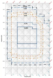
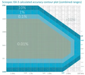
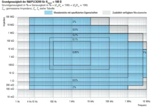
Most manufacturers will specify across a very large range of impedances and frequencies, but a closer look into the datasheet will reveal that only certain range are covered in full accuracy. The distribution of them strongly varies across instruments. Thus, it is important to look at the accuracy-contour plots (see example below) showing which accuracy can be obtained at what absolute value and frequency.
For a detailed comparison of specifications for the most widely used impedance analyzers on the market, check out this article.
Sciospec´s product range
The best solution for broad measurement range, large frequency spans and high-resolution impedance spectroscopy without a doubt are dedicated precision impedance analyzers. Entirely dedicated to impedance measurement Sciospec offers a range of standard lab products and OEM solutions. The Sciospec ISX-3 can be considered the go-to solution and work horse for the majority of scenarios requiring and impedance analyzer. Although
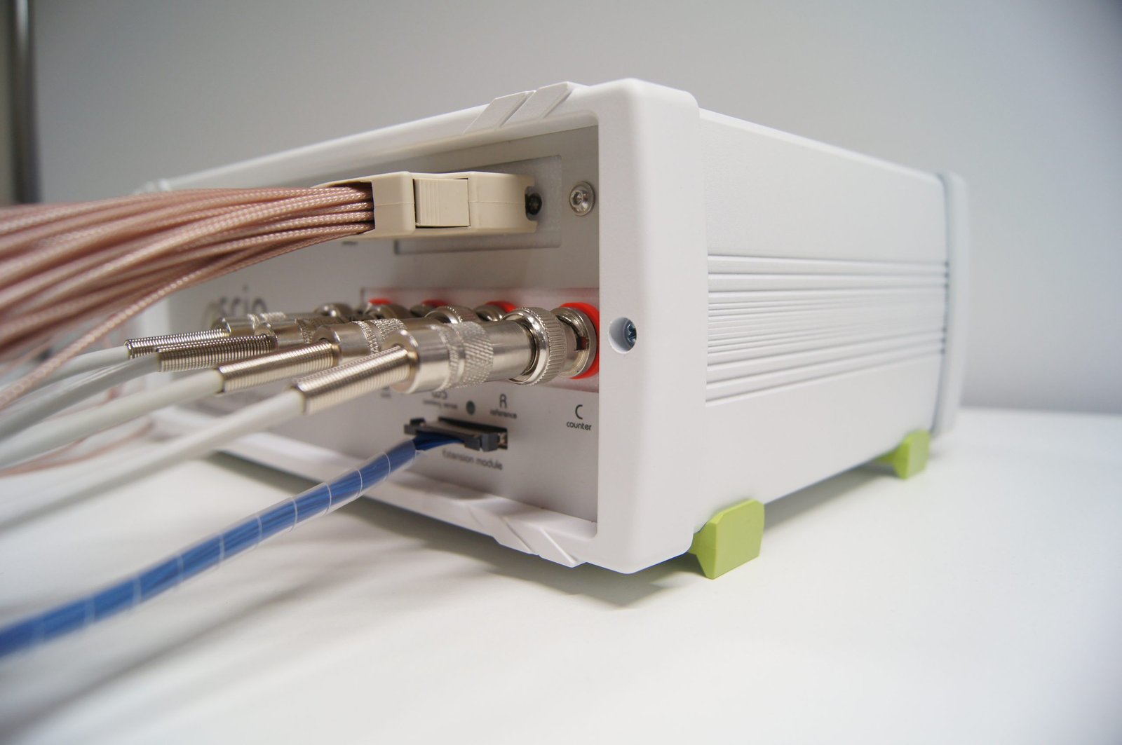
Sciospec offers a broad range of impedance measurement instruments, it is worth to take a look at the ISX-3 to get an overview of technical capabilities associated with impedance spectroscopy. It is a small form factor lab bench single channel impedance analyzer supporting 2, 3 and 4 electrode configurations.
The default range spans from 100 µHz to 10 MHz (optional extension up to 100 MHz) and 1 mΩ to 1 TΩ. Basic accuracy of 0.01% is available between 1 Ω and 1 GΩ up to 2MHz. Very fast measurements can be achieved with a minimum of 300 µs for f>500 kHz. For high-resolution spectra the instrument supports up to 2048 points per sweep. Next to default coaxial measurement ports the instrument also includes a general-purpose extension port for application specific impedance measurement frontends and modules like Sciospec`s multiplexers or sensor adapters.
The port´s specifications and interface are open access enabling users to build their own application specific modules like adapters, multiplexers, fluidic chambers, amplifiers etc. USB, Ethernet or optional wireless interface as high-level interfaces. Additionally low level isolated I/O, serial interfaces and fast hardware synchronization are available for fine grained instruments control. There are many measurement adapters for all sorts of impedance measurement applications and industry standard impedance sensor formats. For even more versatility in impedance measurements, flexible multiplexing solutions and an impedance tomography mode can be added. There is also a medical research version of the ISX-3 that comes with added medical safety features.
Building on the class leading capabilities of the ISX-3 impedance analyzer, the Sciospec ISX-5 is a highly scalable multichannel impedance analyser. It uses the same measurement modules as the ISX-3 but can be extended to 16 fully parallel operating channels. On top of that each of these impedance measurement modules can be extended with all other options we find on the ISX-3. Adding Sciospec´s extremely flexible multiplexer modules to the mix allows for having up to 256 multiplexed ports per module, resulting in a mind blowing 16×256= 4096 impedance measurement ports on a single instrument (refer to the Sciospec multiplexer product page to learn more about the stunning flexibility for multichannel impedance measurement).
Leveraging the full power of Sciospec´s technology platform there are many more options to choose from when it comes to selecting an impedance analyzer. A good example of this is the Sciospec CSX-64 – a 64-channel impedance measurement system with 8 simultaneously acquired channels and any to any channel mapping. It was designed to be the all-in-one solution for chip-based multichannel impedance measurements. With its highly integrated edge card connector interface it’s the perfect fit for impedance based biosensors – they can be either plugged in directly into the ultra-compact low profile system or through a cable adapter. The CSX-64 comes with 8 banks with eight parallel measuring channels each. This enables both fast EIS measurements and more advanced modes like EIT in one highly versatile impedance analyzer.
Highly specialized impedance analyzers for cell based assays
For more specialized applications it is best to design a specific measurement setup. A good example for this: Electrical impedance analysis is a common technique for the readout of biosensing solutions. While there are countless biosensors employing impedance spectroscopy, one class is particularly interesting and challenging – cell based impedance assays. This typically includes living cells cultivated in-vitro in some form of fluidic chamber with electrodes being dropped into the fluidic volume or as part of the chamber’s surfaces.
The most important specific challenges for the measurements in this type of application are sensor contacting, cultivation environment requirements, low signal amplitudes for minimization of biological impact and channel count. Oftentimes these systems require the sensors to reside in an incubator during measurements. This can be a very specific challenge: high quality, low noise impedance measurements require low parasitics and noise coupling – best achieved with the measurement frontends sitting as close to the sensor as possible. Electronics will however inject heat due to their inherent power dissipation and this heat can have a very drastic impact on cell cultures. In very sensitive models often found in organ on chip application deviating as little as 0.2 Kelvin from the target temperature can already be too much.
Another application specific challenge comes with the high channel count requirements. Typical assays will range from as little as eight electrodes (e.g. found in Applied Biophyics ECIS sensors) to 96 well ANSI microplates (e.g. found on the Nanion Cardioexcyte 96 system). Other formfactor sensor arrangements include transwell systems like the NanoAnalytics CellZcope with 24 up to 96 channels or the Mimetas OrganoTEER system for the gel based microfluidic organ-on-chip OrganoPlate assays.
There are however also systems demonstrating that far more channels in a single sensor plate like the 512 channel Sciospec PCOR or EPIX systems. A good compromise between simultaneous read out channels and multiplexing, form factor and incubation requirements, measurement bandwidth and heat injection and many more criteria is essential for good results in these scenarios. As the number one address for impedance measurement solutions, Sciospec is proud to work with the world leading companies for impedance based cellular assays. Our technology is powering systems like the Mimetas OrganoTEER, the Nanion Cardioexcyte and AtlaZ, the NanoAnalytics CellZcope3 and many more.
Get in touch with us
Phone
Headquarters
Sciospec Scientific Instruments GmbH
Leipziger Str. 43b
04828 Bennewitz, Germany
Open in Google Maps